Hostile Vehicle Mitigation Bollards - A Physics Problem
Our page on Hostile Vehicle Mitigation discusses the wider subject of HVM and the supporting activity of Vehicle Dynamics Assessments. One of most visual and familiar aspects of HVM is the bollard. These have been around for a long time, but have continued to evolve in both capability and usability. Below we expand on the types available and how they work.
Core Physical Principles
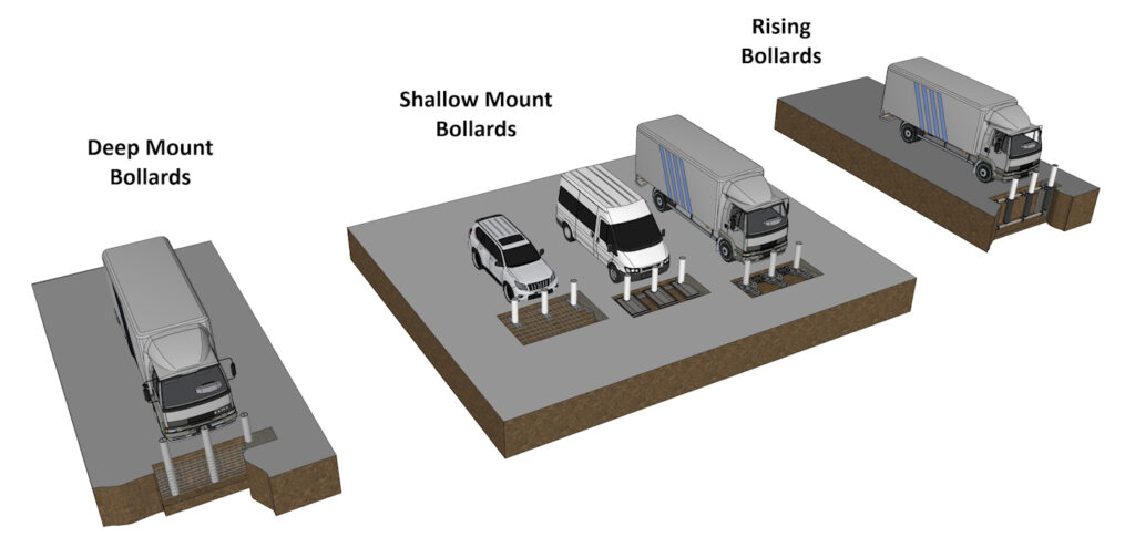
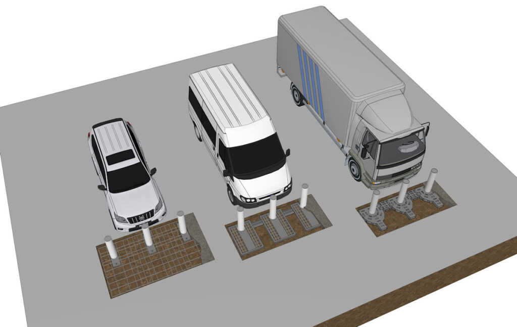
When a vehicle strikes a bollard, forces are transmitted through the post into the anchorage and surrounding ground. Three mechanisms govern performance: energy absorption (plastic deformation of material), energy transfer (load distribution into soil/concrete mass), and energy dissipation (conversion to heat, sound, or movement). Effective design avoids failure modes such as overturning, shear rupture, pull‑out, or bending collapse. The post acts as a load path, but the foundation and soil mass provide the actual resistance; ground strength and interaction are often more critical than the post itself. Although there are myriad different engineered solutions with which to achieve these principles at the higher HVM levels, they fall into three basic categories: Deep mounted, shallow mounted and retractable.
Deep Mount Bollards
Deep‑Mount Bollards: Rigid Transfer and Mass Resistance
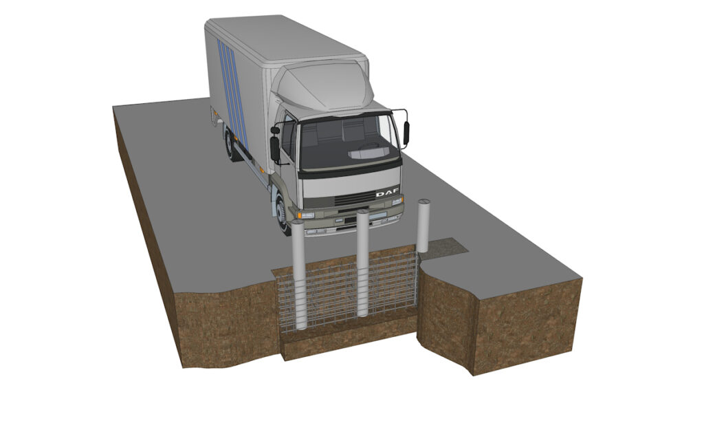
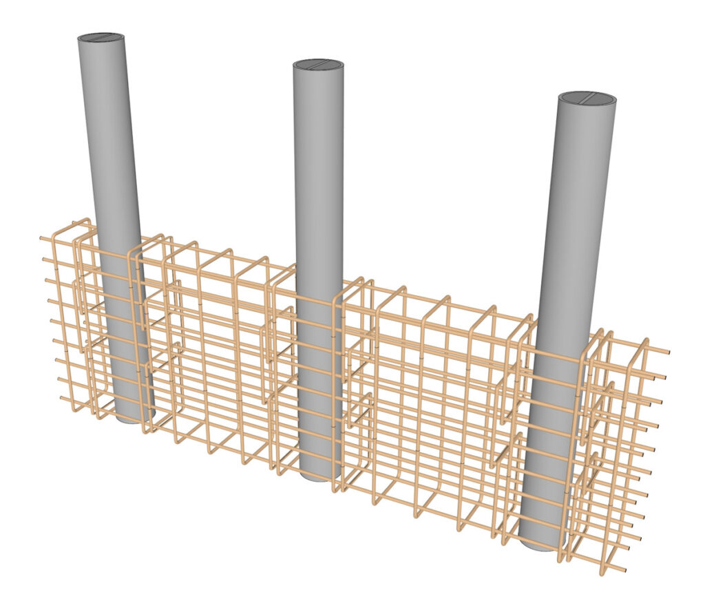
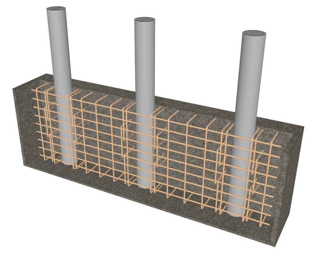
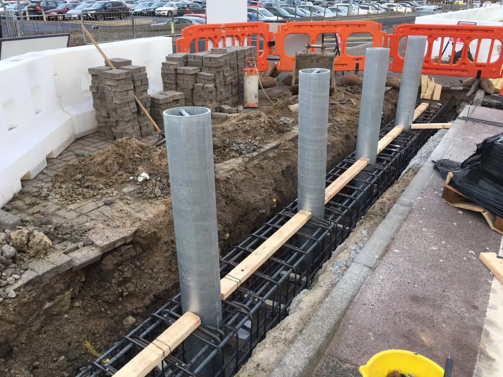
Deep‑mount bollards are the traditional high‑security solution, with foundations typically 900–1500 mm deep, encased in reinforced concrete and connected to a substantial footing or pile cap. Their mechanism relies on rigid coupling and mass reaction. The post is usually thick‑walled steel or concrete‑filled steel, designed to remain essentially rigid, with minimal bending or deformation during impact.
Upon collision, impact forces are transferred directly and almost entirely downward through the post into the deep foundation and then distributed over a large volume of soil and concrete. Resistance comes from passive earth pressure, shear strength of the soil, and the weight and bearing capacity of the foundation block.
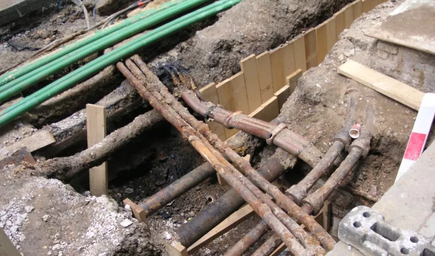
Because energy is not absorbed by the post itself, the system depends entirely on the mass and strength of the ground structure to decelerate the vehicle. This creates a very stiff response, with very small displacement and near‑zero penetration. They achieve the highest ratings (M50/P1 or K12) capable of stopping 7.2 tonne vehicles at 80 km/h, but require extensive excavation and are unsuitable where underground services or poor ground restrict depth. Energy dissipation is dominated by soil deformation and structural shear; failure occurs only if the foundation is sheared out or the soil bearing capacity is exceeded.
Shallow Mount Bollards
Shallow‑Mount Bollards: Controlled Flexure and Energy Absorption
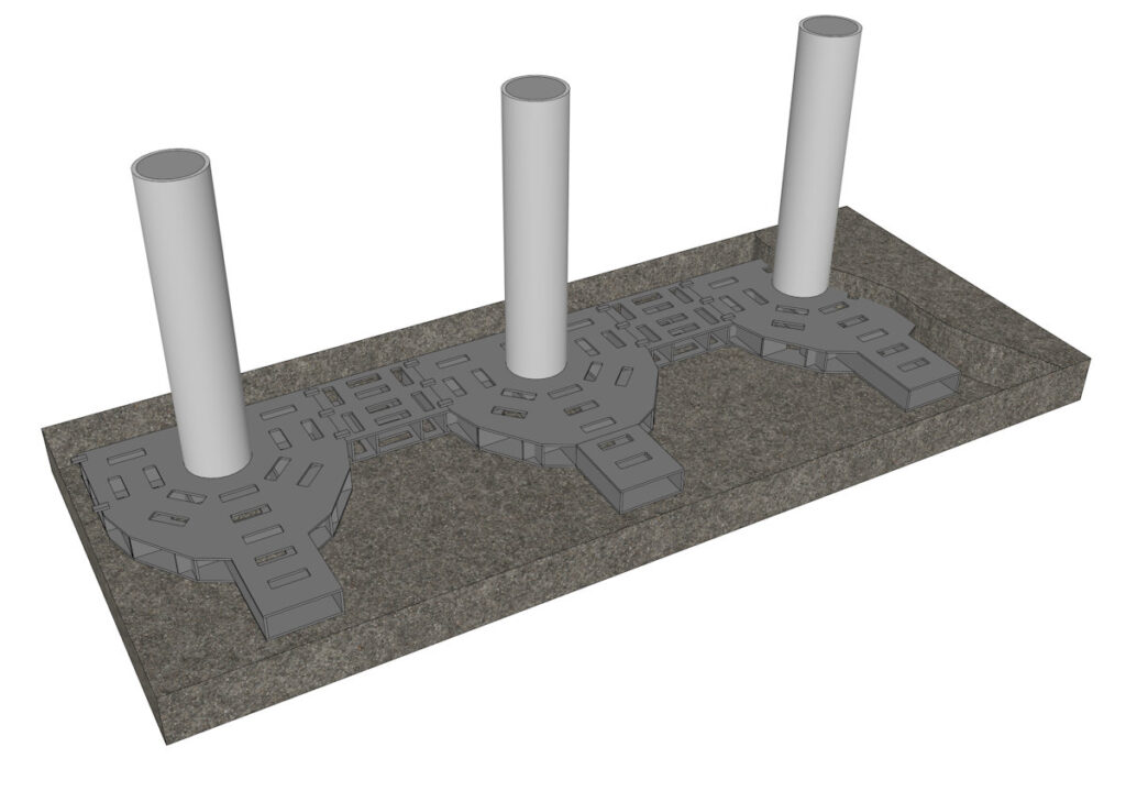
Shallow‑mount designs were developed to overcome depth limitations, with foundations typically 100mm-350mm deep, often installed directly into existing slabs or shallow bases. They cannot rely on deep mass resistance, so their mechanism is fundamentally different: flexural deformation and material energy absorption.
These bollards use engineered materials such as high‑yield steel, composite cores, or spring‑steel sections, shaped to bend elastically and plastically under load. On impact, the post deflects significantly, absorbing large amounts of kinetic energy through controlled bending and yielding. Instead of rigid transfer, force builds gradually as the post flexes, reducing peak load transmitted to the foundation.
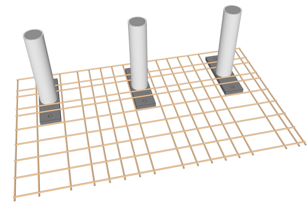
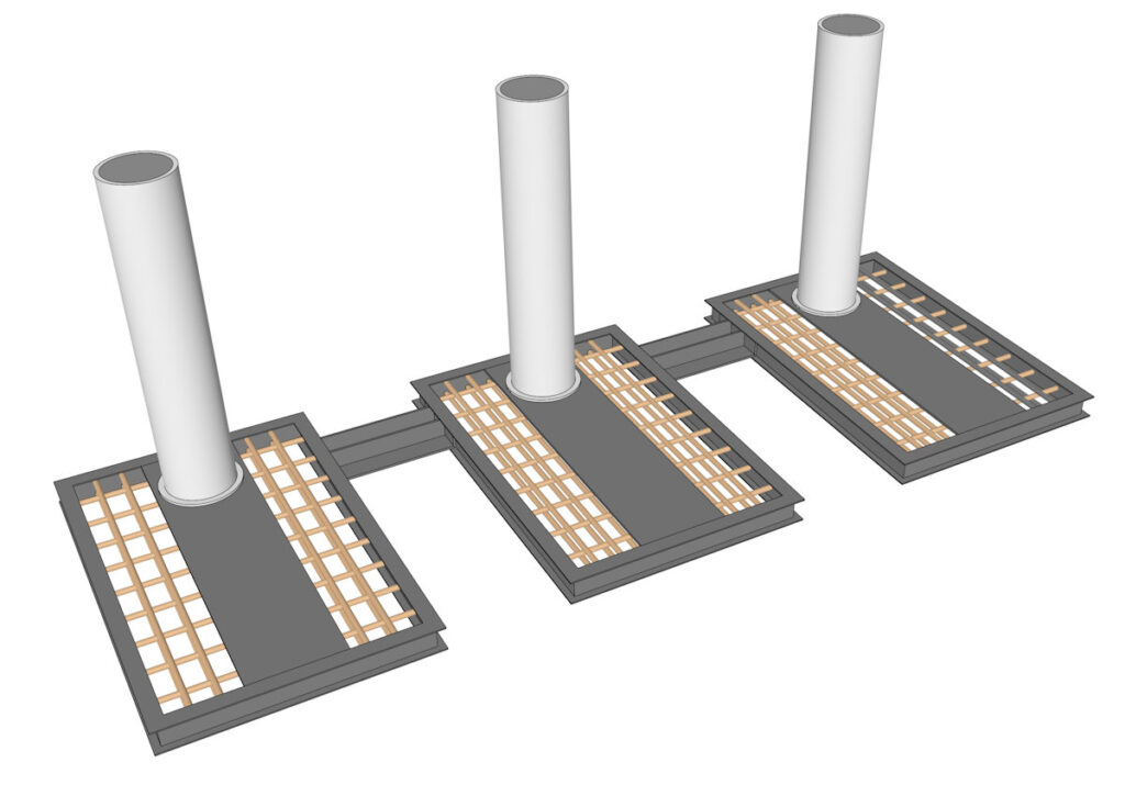
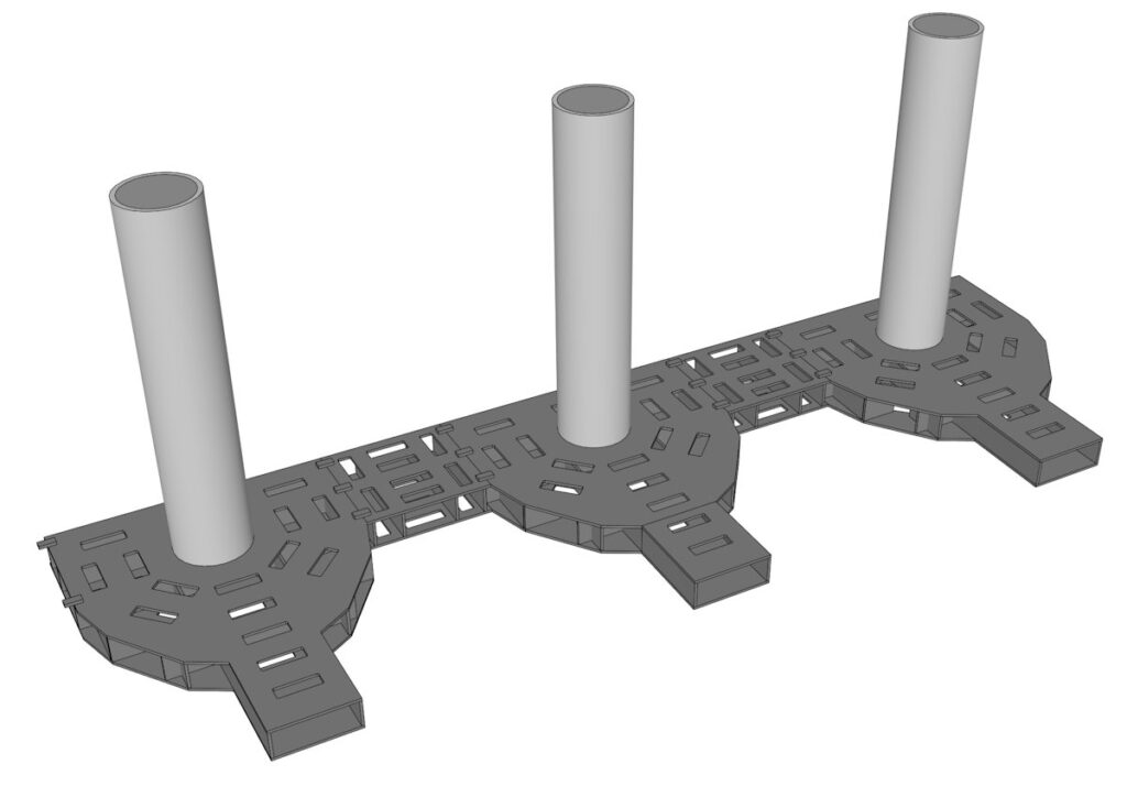
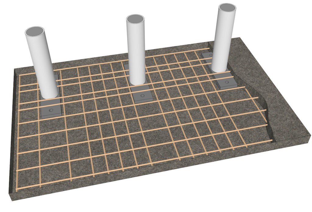
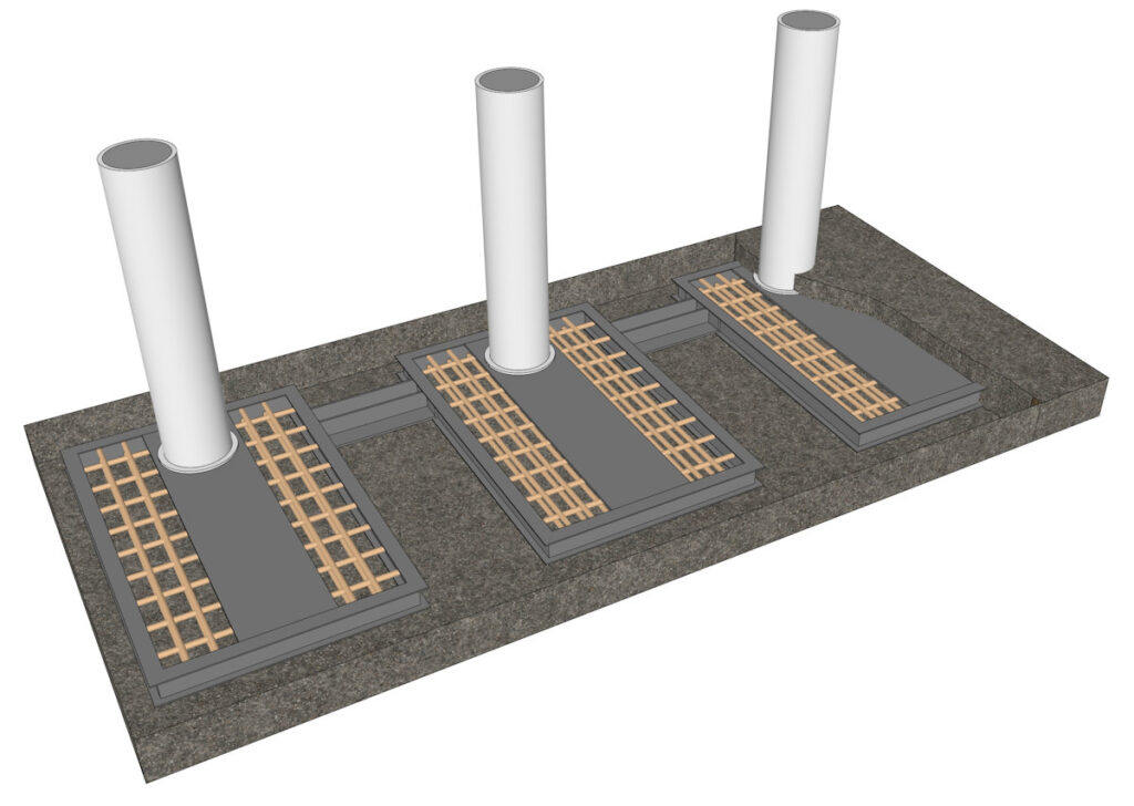
Anchorage is designed to resist moment and shear, not massive downward load; shallow base plates or cage anchors spread load over a wide area of surface concrete or compacted ground.
This system converts energy into plastic strain within the post itself, reducing demand on the ground. Modern designs achieve full M50/IWA 14‑1 ratings with only 300 mm depth, by balancing stiffness, yield strength, and anchorage geometry. The trade‑off is visible deflection and slightly greater stopping distance, but controlled deformation ensures no failure. Mechanism summary: absorb first, transfer lightly. This makes them ideal for urban sites, retrofits, and areas with restricted excavation.
Spreading the load over a larger surface area to resist the bending moment can be achieved in different ways. Shallow-mount bollards have different degrees of prefabrication. Many of them can be simply mechanically attached to their neighbours, automatically creating the industry standard 1200mm maximum clear space between bollards.
Retractable Bollards
Retractable/Rising Bollards: Hybrid Mechanisms with Operational Constraints
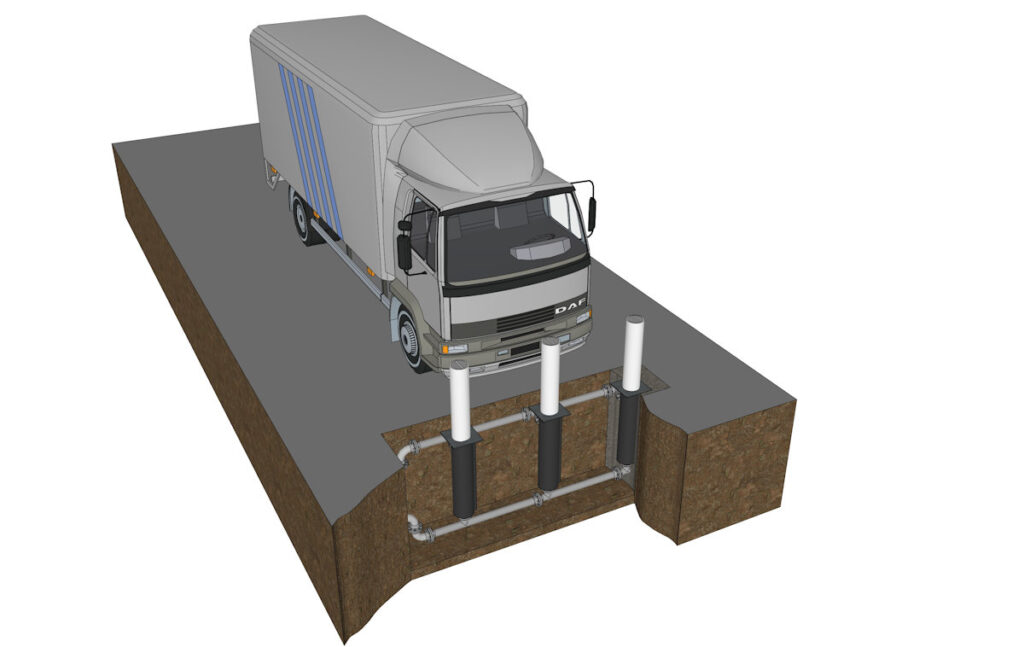
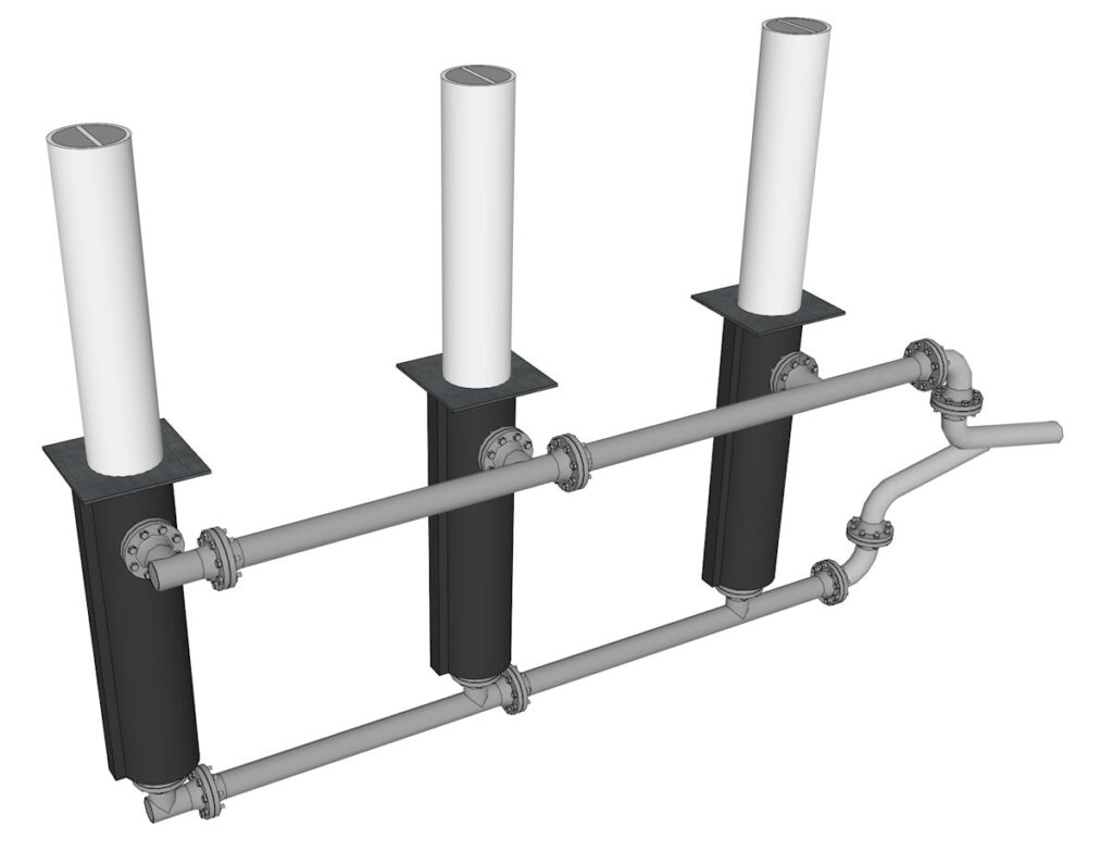
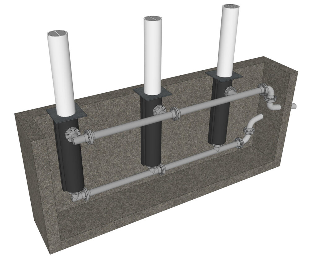
Retractable bollards combine security with access control, housed in an underground cassette and raised/lowered mechanically or hydraulically. Their energy resistance is a hybrid of rigid transfer and internal damping, but limited by the need to move.
When raised and locked, the post engages with a reinforced sleeve or base frame embedded 400mm-800mm deep. Unlike fixed deep‑mount types, the load path includes mechanical interfaces such as locking pins, guide tubes, and hydraulic cylinders, which introduce compliance. Impact energy is managed in three ways: partial transfer to the foundation via the outer casing; controlled deformation of the post or internal structural elements; and, in hydraulic versions, energy dissipation via fluid compression or bypass valves.
Key differences from fixed bollard types: the system has more components and joints, creating potential weak points. To compensate, retractable bollards use thicker walls, reinforced locking mechanisms, and sometimes sacrificial sections that deform predictably to protect the housing. Energy absorption is shared between structural yielding, friction in guides, and hydraulic damping. They are rated up to M40/K8, suitable for medium‑to‑high security, but generally not the highest M50/P1 ratings, because the moving mechanism cannot match the rigidity of a monolithic deep foundation. Critical physics constraint: the cassette and surrounding concrete must be strong enough to resist lateral forces without splitting or shifting, while allowing operation. Failure modes include locking mechanism shear or casing deformation, issues unique to this type.
Retractable, or rising bollards are essential for providing controlled access to an area. A common such use is access into a pedestrianised area for delivery to the shops within. The bollards might be lowered within specific time limits or access might be on a vehicle by vehicle basis. There are many technologies that can be used for access control and they can be applied here. This might be ANPR, an approved key fob, discussion over intercom to a control room and more.
This access control comes with an elevated cost of ownership. This is exacerbated by the increased maintenance requirements for hydraulics or electric motors, lubrication and clearing out sand, organic detritus and salt from between the moving elements. They can also have issues with water ingress, the effect of which is compounded if it freezes.