Landmines – All You Never Wanted to Know

Landmines

Landmines - A Resource

Over the years, Steve Holland of SJH Projects has been involved in many projects connected with landmines, which has resulted in a collection of useful data and resources. The intention of the content below is to use this experience to provide a primer for some of the issues and terms relating to landmines, the protection from them and and associated test methodologies.

Background

Definition

A landmine is an explosive device activated by a person or a vehicle, or command-detonated by electric wire or radio signal. Most landmines are laid on or below the surface of the ground. Normally manufactured from durable materials such as plastic, bakelite, concrete, glass or metal, landmines are designed to survive the effects of weather, seasons and time. The purpose of landmines is to disable, immobilise vehicles or kill people. – Dag Hammarskjöld United Nations Library.

History

The first use of what we call landmines was in 1862 in the US Civil War. Invented by Confederate Brig. Gen. Gabriel Rains. They were pressure operated devices named ‘Torpedoes’, Based on 8” & 10” inch shells with pressure initiation. General Sherman claimed that their use was “not war but murder”.
Landmines History
General Rains, the 'Torpedo' in action and General Sherman
WW2 and area denial – the onset of what became the established tactic was by Finland in 1939 to slow and channel the much larger advancing Russian forces. Widespread use of such area denial was then undertaken in the Western Desert to put some control on the battlespace. The main threat deployed in these instances was the anti-tank mine but as these were relatively easy to detect and either lift or defuse, they were protected by smaller, harder to detect anti-personnel landmines
Landmines - WW2
Russian advance into Finland, clearing bounding mines in the Western Desert, mine damaged Panzer

The evolution of anti-personnel landmines has been towards a minimum quantity of metal to inhibit detection. The larger, buried blast AP landmines are big enough to very seriously injure or kill those whose step on them. Many however are small in explosive content and are designed to just wound the victim. A wounded soldier takes up more resources to evacuate and treat thus contributing to a slowing of the enemy’s advance.

Since WW2 the landmine has been used around the world, sometimes in planned, well marked minefields that help with post conflict clearance, but they have also been used indiscriminately leaving large swathes of country polluted and too dangerous to occupy or farm by the local population. Treaties have been put in place to ban their manufacture and use but not everyone signed up and millions of legacy landmines are still out there.

Landmines - Map

Estimates of over 100 millions mine emplaced worldwide.

71 countries afflicted with landmines.

2000 victims of landmines every month (one victim every 20 minutes)

Landmine Types

Landmine Types
Anti-tank, Anti-vehicle and Anti-personnel Landmines

Anti Personnel Landmine Types

Within the classification of AP landmines there are some very different mechanisms of action and injury. 
 
Bounding Mines

Bounding Mines:

These are designed to spring up to a height of about 1 metre and then fire out steel balls radially to hit the limbs and torso of the victim and anyone else within close proximity. Lethality and injury is driven by the fragments more than blast which dissipates quickly in such a free air, unconfined environment.

Stake and Claymore Mines.

These are both ground based fragmentation landmines. The stake mine acts radially whereas the Claymore is designed to be directional and is mostly used to protect occupied positions or specific route denial. The Claymore can be set to be victim operated or by demand by troops in defence.

Spike Mines
Buried blast Mines

Buried Blast Mines:

These are the ones that cause the biggest legacy and clearance problem. They are the ones mostly responsible for lower limb injuries and amputations. The charge size spans from the Russian PMN at 240g explosive content which is trying to kill the victim, through to the PMA-2 of with100g down to the M-14 US landmine with 28g which is designed to wound.

Anti Tank / Anti-Vehicle Landmines

Anti-Tank Landmines
Larger anti-tank/vehicle landmines are designed to target everything up to main battle tanks. They include basic blast mines and the more deadly penetrator types. With these, the explosive charge projects a thick copper disc which deforms to become a very high speed, high mass projectile aimed at the underside of the vehicle. This technology has been adopted to create off route devices to attack the sides of vehicles and has become the basis of a very popular form of IED, being produced on an almost industrial scale.

Ground Effects

Landmine Blast test rig

The ground in which a landmine is buried has a huge effect on how much blast energy it delivers to its victim. 

The shock wave will propagate through the landmine from the detonation point but it will basically act as an expanding sphere of hot gas, driving a shock wave ahead of it. Dry, loose sand will allow the downward facing portion of this sphere to penetrate and dissipate with some minor reflection back upwards. Hard packed, sun baked earth or saturated clay are very resistant to such downward effects and reflect a lot this energy back upwards amplifying the energy delivered to the victim. 

A lot of solid science was done on this subject by the DRDC in Canada with its pendulum arm. Establishing valid, repeatable ground conditions was a key factor in setting test standards for the assessment of protection measures for both anti-personnel and anti-tank landmines.

Anti Personnel Landmine Injuries and Treatment

Injury Patterns

Injury Patterns

Injury Distribution

Landmines can cause a variety of injuries, so it is important to have an understanding of where the predominant issues lie. The image shows the distribution of injuries observed during a HALO study in Kuito, Angola between January and October 1995. It can be seen that limb injuries are by far the most common form.

The ICRC (International Committee for the Red Cross) have a general classification system for antipersonnel landmine injury patterns.
landmine injury, pattern 3, forearm damage
Pattern III: Usually from handling a landmine or from detonation in close proximity when in the prone position.
landmine, pattern 2 injury
Pattern II: Either from a fragmentation mine or from ‘contra-lateral’ effects of a blast mine and secondary fragmentation.
landmine injury, foot and ankle
Pattern I: Direct lower extremity contact with pressure plate operated blast mine.

Pattern I: Injury Mechanism

landmine injury, pattern 1 wound
Robin Coupland ICRC, Proposed mechanism for Pattern I damage.

Total disruption of foot / ankle complex.

Contamination of soft tissues higher up.

Propulsion of soil and fragments up tissue planes.

Contusion to muscles.

landmine injury, lower leg tissue damage

Amputation Level And Ongoing Function

landmine injury, above knee amputation

An above knee amputation (left) requires about 100% more energy to walk.

A below knee amputation requires about 15% more energy to walk and so provides greater quality of life. 

Image right is Chris Moon MBE on his way to complete the Marathon des Sables. 
 
Crhis Moon MBE

Social Factors and Clinical Choices

It is a fact of life that the most appropriate surgical choice will be informed by social factors. There will be scope for complex, repeated surgeries in advanced facilities and extended recuperation and rehabilitation if the patient is part of a western military or highly insured NGO worker. This may ‘save’ the limb albeit quite likely with some restricted function. A local subsistence farmer could not afford that time away and the loss of earning capacity and so a rapid, appropriate level of amputation and a well fitting prosthetic will allow him to get back to work and looking after his family in a much shorter time frame.
Landmine injury, methods of Ilisarov cage
landmine injury, prosthetic leg

An example of the potential long term reconstruction is the ‘Methods of Ilisarov’ which is focused on the long bones. After such effort it is not unheard of that the apparently healthy looking limb is largely insensate through nerve damage, even to the level that the owner is eventually driven to request an amputation. 

A quality, modern prosthetic will actually provide more mobility and ongoing quality of life. Soft tissue and especially nerve damage is much harder to treat with current medical technology.

Surgical Treatment of Pattern I Injury

As presented by vascular surgeon Eddie Chaloner at the UK Defence EOD School, Dec 2001.
 
  • General resuscitation of the patient with intravenous fluids or blood.
  • High dose intravenous Benzyl Penicillin
  • Ant-tetanus toxoid
  • General Anaesthesia
  • General Wash of the legs
  • Use of above knee pneumatic tourniquet to minimise blood loss.
  • Amputation above the level of devitalised and contaminated muscle.
  • Thorough debridement of soft tissue injuries
  • Leave the wounds open
  • Bulky absorbant dressing
  • Oral antibiotics post operatively
  • Back to theatre at 5 days post op
  • Closure of wounds if clean with no tension
  • Skin grafts to large open areas
  • Early physio to prevent knee joint contracture
  • Further physio to develop upper body strength until prosthetic fitting
  • Adequate prosthetic service with replacement follow up.

Anti Personnel Landmine Protection Measures

The Hands, Torso and Face

demining prodder
Combined prodder shield and hand protection
demining apron
Typical configuration for a demining apron
demining helmet
Lightweight helmet with integrated blast and fragmentation visor.

The majority of equipment designed for protection against buried AP mines is focused on the needs of those involved in their clearance.

The hands are are closest to the threat and are at risk of ‘de-gloving’ which involves the skin and tissue being stripped away by the blast. This can be mitigated by well fitted gloves using a high strength fibre such as an aramid. It is critical however that such protection must not reduce dexterity and ‘feel’. A lot of manual clearance uses prodding and such prodders can become secondary projectiles. Chris Moon MBE lost his hands when the prodder he was carrying was projected upwards through his hand. The integrated prodder and conical shield shown is a viable approach as it diverts the blast away from the hand and the materials used provide protection from the fragmentation. There will be some rapid loading applied to the hand and lower arm but this manageable and preferable to the alternatives.

The greatest proportion of landmines are in hot countries. To minimise the heat stress to deminers, most protective aprons and ensembles account for this by having an open back. It is assumed that if procedures are being followed, the threat will come from in front of the operator. The protection needs to facilitate ease of transition from walking to kneeling and lying prone. The prone position exposes the top of the shoulders to line of site of the blast which is accounted for by large shoulder pads.

The threat to the head and eyes is a combination of blast and fragmentation. Even small blast mines have a casing and throw out the dirt and stones in which they are buried. Lightweight, heat dissipating helmets provide support to impact resistant visors. These visors need to be highly scratch resistant so that the operator is not tempted to lift them (it does happen). If the visor is in a raised position it no longer stops fragmentation and it will capture blast pressure and rotate the head backwards. How injurious this is depends on the very specific circumstances of the individual event.

Footwear

The challenges associated with the protection of the foot and lower limb from buried blast mines are more complex than for other parts of the body. There is a direct coupling between the foot and charge, creating a load path for a lot of energy applied instantaneously. This energy needs to be managed whilst also preventing heat, gaseous and fragmentation effects. In this instance, the fragments can include the mine casing, the soil used to bury it, the sole of the footwear and bones of the foot itself being projected upwards into the rest of the leg.

Like any protection system, AP landmine protection footwear needs to balance conflicting demands. These are the protection level provided, the resulting mobility of the user and the financial aspect – the NGO demining community and even the military do not have limitless funds and have to provide the best affordable protection to the greatest number of users. There have been a number of attempts to produce effective mineboots and they have addressed the trade off in different ways. The models shown below were the key ones when we were actively involved in this area – some of the brand names have changed but after an initial surge in creativity, the market and its offering has not evolved much since.

landmine protection boot, Israeli

MICS – Israel

This works on the basis of prevention being better than cure. The weight of the wearer is spread such that the ground pressure is not enough to trigger the device. It also provides some height stand-off between the device and foot. Later versions include some protective materials.

landmine boot research, human limb

Spring Steel – Serbia

This was sent by allies in a mine action centre and included in a series of tests with human limbs. The protection was provided by a full sole of thin spring steel. It was the only system tested that made the injury worse than a standard combat boot. The steel sheet effectively collected the available energy and delivered it all into the structure of the foot. Image right is that limb post test.

human leg, landmine test, blast research
Landmine protection boot and overboot
Landmine protection boot, Wellco

Wellco Boot & Overboot – USA

An early entrant, this is now in a second generation. A boot and overboot of similar sole construction were available. The sole featured a shallow ‘V’ to deflect blast and that V was filled with crushable honeycomb to absorb some energy through mechanical work. Cadaver tests showed that it provided some protection against the smallest AP mines. The addition of the overboot added protection but reduced user mobility. The later version had broadly similar performance but was a more robust design and a better quality of build.

BFR Boot – Singapore

The BFR boot enjoyed commercial success in the early days of the expanding market. Looking like a normal combat boot with uppers to suit local climates and competitively priced it provides modest protection from smaller AP mines. It features an aramid fragmentation protection layer and mechanically compressible forefoot and heel section. These sections do dissipate some energy through mechanical work. The boot does not feature any shaping of the sole or stand off over and above a normal combat boot, so is reliant on this construction and materials alone. The trade off being towards mobility rather than protection is valid if that it is what the customer requires for their particular needs. For general military in a non- specialist mine clearance or combat engineering roles this is understandable. For dedicated high risk roles, less so.

Landmine protection boot, Wellco
Landmine protection boot, BFR
landmine protection boot, Anonymate

Anonymate – France

This French entry into the market pushes the sole ‘V’ shaping and increased stand-off as the key to protection. The outlying blocks are for stability in normal use and detach quite easily under blast loading so as not to interfere with venting of the hot gases. Computer modelling of the flow of soil and gases under explosive loading has been extensive in investigating the performance of this design. Protection is reasonable but it is no longer a design suitable for general military use.

Zeeman – Germany

This was a later entry into the market and the design was decided upon after assessing the benefits and perceived shortcomings of existing designs. It goes for a materials rather than shape based solution with a manageable stand off along its length. Although it features a traditional looking boot upper, it is not suitable for infantry type roles. The published testing seen did not use suitably biofidelic limbs or instrumentation but its position in the performance spectrum can be broadly assessed from the mechanical limbs used.

landmine protection boot, Zeeman
Landmine protection boot and gaiter

PPE100 – United Kingdom

This design is intended for specialist demining high threat use from the outset. It uses blast mitigation material and a fragmentation protection layer in the sole, both of which also contribute to stand-off. The boot shell, based on a mountaineering boot provides good support to the ankle complex. A removable inner boot provides cushioning and can be replaced to extend the life of the system as a whole. Knee high integrated gaiters provide fragmentation protection to both the impacted limb and to the adjacent limb (Pattern II Injury). Development testing was undertaken with amputated human lower limbs, restricted to move in a single vertical axis. Different instrumentation was employed to investigate correlations between measurements and clinical outcome. Work on this project contributed to improvements in design of biofidelic mechanical surrogates. This work also led to the invitation of Steve Holland and Eddie Chaloner onto the NATO Human Factors in Medicine, Technical Group TG024 to help define better test procedures.

Med-Eng Spider boot

Med-Eng, Spider Boot – Canada

Built around decoupling and stand off the Spider boot is a modern iteration of an ad-hoc design from World War II. There is no direct load path from the landmine to the foot and the ‘leg’ that impacts the mine will be blown away ensuring disconnection. Larger than one might, think the footplate hinges to aid movement but this is definitely a design that emphasises protection over mobility. It is a deliberate positioning in a niche sector of the market place without compromise. In this, it is very effective.

Landmine protection boots, Holland WW2

Ranking

The slides below are extracted from a presentation given by Steve Holland of SJH Projects on behalf of NP Aerospace at the prestigious ‘Personal Armour Systems Symposium at the Royal Armouries in Leeds in 2006 The subject was a joint venture that took place at the time. The slides show a qualitative ranking of the boot offerings discussed above with respect to their protection level and their mobility. Different test data was in the public domain for each design and the scientific quality of that testing varied but was enough to draw personal conclusions.
Landmine protection boots, comparison table, performance
Landmine protection boots comparison table, practicality

Anti Tank Landmine Damage and Injury Mechanisms

Landrover, IED damage
AEp55 demonstration creash test dummy
Rear face scabbing from blast
Stryker, buried IED strike

There are many ways in which hitting an anti tank/vehicle landmine can result in death and injury and some of the key, predictable ones will be discussed here. Outside of these key issues there is always the unpredictable nature of the road traffic accident you are about to have even if you survive – this can end up in a side impacts, a rollover, fire and has even resulted in death by drowning in irrigation ditches.

The most obvious mechanism is that the blast breaches the floor of the vehicle, directly exposing the occupants to very high blast overpressure, heat and fragmentation. The torn and damaged floor structure can contribute to that fragmentation. Just outside of where the floor is breached it can undergo excessive deformation into the lower limbs and back of the occupants.

The next two mechanisms are in which the floor essentially maintains its integrity but with consequences. A rigid vehicle floor can act like a thick drum skin and undergo high speed vibration which kicks up anything that was sitting on the floor such as poorly stowed equipment. The tools shown in the image with the crash test dummy were left on the floor deliberately to illustrate this point. This has been used to illustrate the importance of discipline in equipment stowage. The rapid, local floor deformation and shock transmission can be enough to cause such tension in the back face of the floor that metal ‘scabs’ to come away and be thrown upwards at high speed.

A vehicle can be designed to resist the blast shock wave that would result in hull breach, and so look as as if it has defeated the landmine. The impulse of the explosive event might still be sufficient to lift and throw the vehicle. This rapid upwards acceleration creates a range of potentially lethal human factors which have become the focus of a lot of vehicle blast mitigation design, both in terms of the overall structure and internal fit out.

Human Factors and Vehicle Impulse

The NATO document AEP55 Volume 2 (more of which later) gives five Mandatory Survivability Criteria to determine pass/fail in vehicle blast tests.
AEP55 Vol 2, Mandatory criteria table

Lower Leg

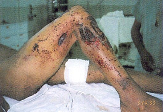
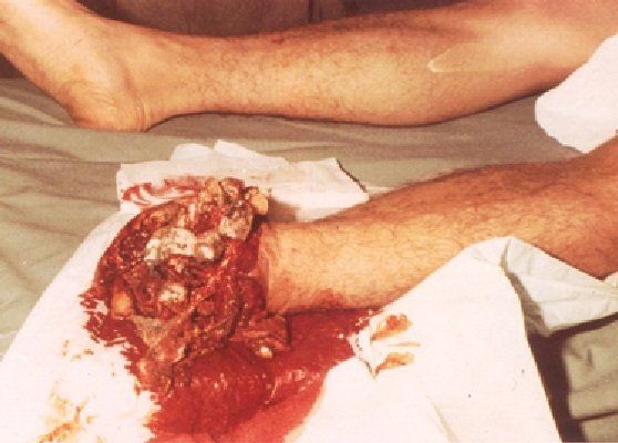
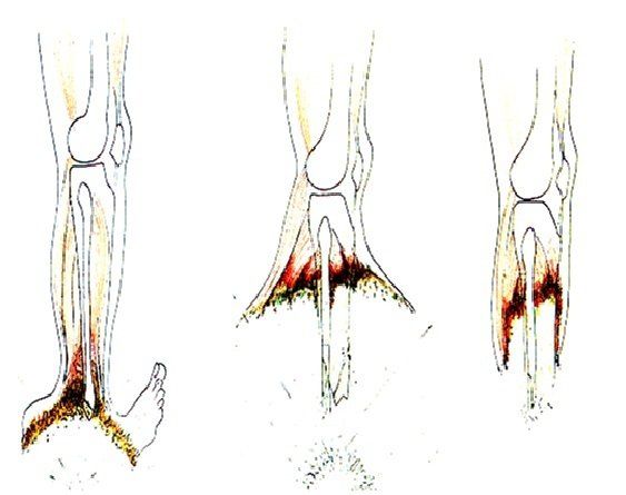
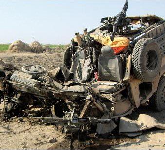
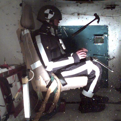
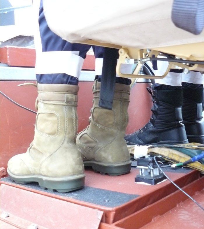
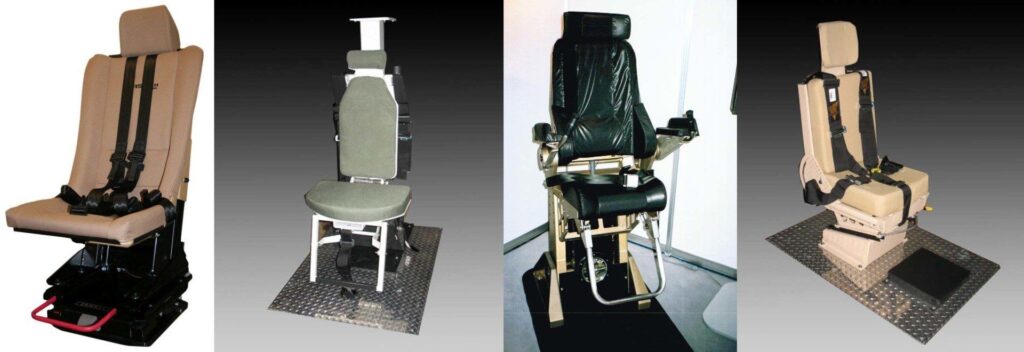
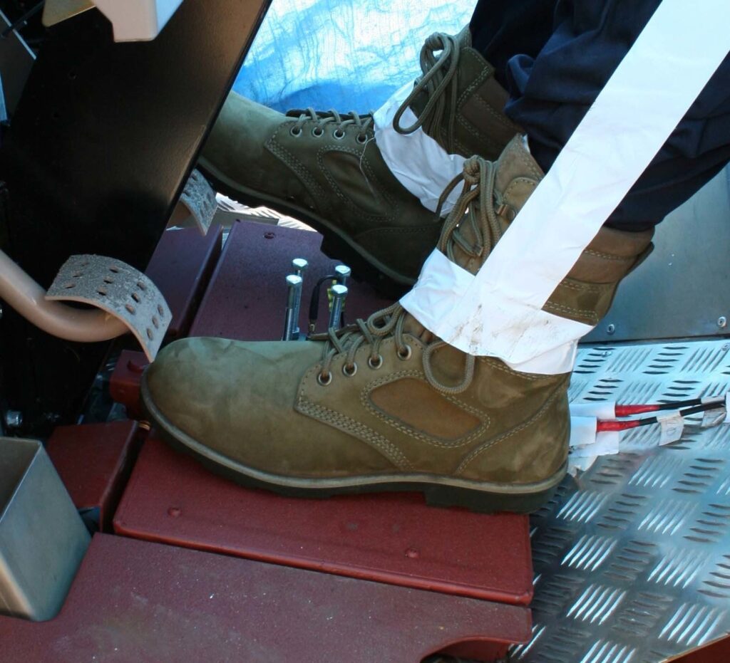
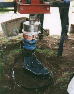
Even with the best crash worthy seat available, the lower limbs can be exposed to rapid loading through floor deformation and transmitted shock. It is also worth bearing in mind in that in remote locations, with poor sophisticated medical back up, severe lower leg injuries can be fatal. A mere ‘broken leg’ can become a much larger issue.
Hybrid III lower leg
Measured on the upper tibia load cell of a Hybrid III ATD (crash test dummy) the load threshold matches an Abbreviated Injury Scale of a moderate injury. The legs of the ATD should be set as vertical as the set up will allow with feet on pedals where appropriate. This maximises the axial load. Actual injury to an individual will depend on bone strength, weight, attitude of foot and footwear.
Landmine testing, jackal footpad accelerometer

Thoraco-Lumber Spine

The human spine is a complex structure which can take high longitudinal acceleration for a short duration and lower g values for longer, but it not a linear relationship. Called the Dynamic Response Index (z) it is derived from an accelerometer set into the base of the spine of the ATD.
Hybrid III, base accelerometers
Spinal accelerometer of Hybrid II
AEP55 Volume 2, axis system
ATD Axis system for AEP55 Volume 2
vehicle IEd injury, human spine
The complex curvature of the spine
AEP55, crash test dummy, ATD

Cervical Spine

There are two very different criteria relating to the neck. The first is axial compression, which is similar to the DRIz at the lower spine in terms of the acceleration/time relationship and the second is forward/rearward turning moment (whiplash).

An interesting issue with this is the helmet. It is obviously required protect the skull from all the rapid movements and potential impacts that can happen during a landmine event. In terms of neck axial loading it does eat up headroom which, depending on the vehicle layout, can increase the chance of hitting the ceiling and adding to the axial load.

The mass of the helmet itself will provide some inertia to the combined mass supported by the neck. This will contribute moderately to the axial load and in a much bigger way to the turning moment at the neck. Tests are conducted with the head in an upright position but should the occupant be leaning forward, this whiplash effect would be much more significant.

Overpressure Effects

For both closed and open topped vehicles, overpressure can be injurious. The mandatory criteria looks beyond the effect on pressure sensitive ears to the more life threatening mechanism of chest wall velocity and the transfer of shock to the lungs and other internal organs.

The short duration of this pressure loading means that air in the lungs cannot vent though the mouth and nose. Because of this, the chest wall moves inwards, the internal pressure increases, the chest and abdomen become stiffened and so provide increased resistance to further inward movement. This complex relationship is calculated by an established chest wall velocity prediction calculation that uses input from an external chest mounted pressure gauge. For simplicity this pressure gauge is set on the outer face of any body armour that the ATD will be wearing.

AEP55 chest pressure measurement

Anti Vehicle / Tank Landmine Protection Measures

Although landmines have been in widespread use since WW2 it is only in more recent times that protection systems have been properly engineered based on clinical data. The preceding systems tended to be improvised such as sandbagging vehicle floors or the addition of extra armour plate. In the same way the landmine boots used different approaches, vehicles have done the same.

Floor Shaping

landmine protection, v shaped hulls
Designing a vehicle around a V hull was pioneered in South Africa and it continues to be a useful part of the protection matrix. Taking it to the extent that the South African’s did,  compromises internal usable space and results in a taller vehicle neither of which are desirable for general military service. The protection levels however were impressive.

Blast Mitigation Materials

Landcruiser with Minesheild system fitted

Blast mitigation used in connection with ballistic materials, offer a weight advantage over steel and have been for retrofit solutions both in the NGO demining support support sector and for deployed military vehicles as part of an enhancement package. To see more on the SJH Projects XPT material and the Mineshield Click Here

vehicle blast shield, Mineshield

Seating

blast protection seats
One of the most significant advances in protection technology arising from post 9/11 conflicts is the rapid rise and improvement in blast mitigation seats for vehicles. Featuring integrated four (or more) point harness to keep the occupant contained they feature a range of solutions to manage the damaging vertical acceleration discussed above. The seats tend to work on the basis of a controlled collapse that smooths the initial spike in acceleration and then brings the occupant up to the same velocity as the vehicle such that the DRIz is not exceeded. Newer generation seats allow the user to dial in their weight so that the maximum benefit is extracted from the protection mechanism.
landmine blast, vehicle footpad

Footpads

Crushable footpads isolate the foot from the floor and can be tuned to crush at the right rate of loading. This expends energy through mechanical work thereby reducing that delivered into the foot and ankle of the user.
Ten Cate, active defence system

Active Systems

A fast detection and firing system makes it possible, but complex, to fire blast energy at an equal and opposite amount to cancel out or at least minimise the vertical impulse on the vehicle. This is an emerging technology.

Testing and NATO Technical Groups

Historically, the protection of vehicles and personnel against blast has been an active area of research interest amongst the NATO members and other key players such as the Australians. The active member countries sometimes worked on joint programmes and sometimes alone. For each programme the test aims, start conditions, measurement regime and interpretation was determined locally with valid assumptions. The issues arose in trying to directly compare results from one test with another performed elsewhere. It also resulted in tests having to be repeated around NATO to meet each members specific criteria. This was hardly efficient and was inhibiting the build up of useful large data sets.

To address this shortcoming, an Exploratory Team meeting ET007 was held at the Queen Astrid Military Hospital in Brussels in February 2000. This meeting included the research communities for vehicles and for dismounted personnel at risk of stepping on AP mines. The outcome of this meeting was the setting up of Technical Group 024 (TG-024) which would focus on anti-personnel landmines and TG-025 which would focus on underside blast threats to vehicles. Both would have to address similar issues in setting up a suitable test frameworks but did not always draw the same conclusions.

TG-024

Test Limb Surrogates

The proliferation of AP landmines in the Balkans wars was the catalyst for research in AP landmine protection and boot development. For the testing of these new products, industry and government used a range of surrogates to mimic the live human leg.

Mechanical Surrogates

landmine protection boot, test rigs
Mechanical surrogates are often simple, robust and most usefully repeatable in their response. They can give comparative data but are generally not very useful in correlating a given result to a clinical outcome. They are best used to perform quick and simple sifts of potential boot/overboot construction candidates for examination by more accurate means at a later stage.
landmine protection boots, animal bone surrogate limb

Animal Models

There is no natural mimic of the human foot within the animal kingdom. Useful work was performed by DSTL Porton Down using deer bones to produce a simplified version of the foot, ankle and tibia. Deer bones were selected for the their proportions and mechanical properties. The skeletal assembly was cast within ballistic gelatin – long used as a soft tissue surrogate for defence applications. The foot like assembly does offer the opportunity for some form of clinical comparison and imaging.

Human Cadaver

Work with human cadavers was undertaken by the USAIR (US Army Institute of Surgical Research) in San Antonio as part of LEAP (Lower Extremity Assessment Programme). The use of cadavers in this way is only really practical in the USA. They have the means to overcome the constraints of finance, ethics and cadaver availability. The outcome of LEAP was a wealth of data that provided clinical effect reference points for charge sizes, ground conditions, position under the foot, orientation of the body and its applied weight. It also pushed the boundaries of techniques for instrumenting organic tissue to capture data that correlates to injuries both in the bones and soft tissues.
landmine protection boots, cadaver tests
landmine protection boot, amputated human limb
landmine protection boot, human limb testing

Isolated Human Limb

This was the project in which the author was directly involved with the support of UK vascular surgeon Eddie Chaloner. He had worked in landmine injury treatment worldwide. This work on amputated human limbs was very effective but did show up the key shortcoming any any human tissue work which was variability. The limbs were from a wide range of ages, both genders, size and condition – robust healthy limbs tend not be removed from their owners. This work did inform key improvements to frangible surrogates later on.

Computer Modelling

During the period covered by TG-024 computer modelling was starting to be useful and certainly showed promise. Validation tests did show differences which the modellers attributed to shortcomings in the tests – otherwise known as the real world. If reference data of the right quality can be sourced,FEA modelling of this nature will become the default for development work.
landmine protection boot, computer modelling
Frangible synthetic limb, human test leg

Frangible Surrogate Limb

The FSL or ‘Frangible Surrogate Leg’ is designed to mimic the behaviour of a human leg under the rapid loading experienced when you step on an anti-personnel landmine or are in a vehicle hit by an IED.

By having bones that break at the same levels and in the same way as human bones and by taking measurements of the forces experienced, it provides invaluable information to both clinicians and engineers. This data will help in the development of systems to protect the lower limb for both mounted and dismounted personnel in areas in which landmines and buried IEDs may be found.

To see more on the FSL Click Here.

Frangible Synthetic Limb, exposed bones
CLL, synthetic test limb

Complex Lower Limb

The Canadian ‘Complex Lower Leg’ features a double calcaneum which seems less bio-fidelic but does automatically double the sample size which is most useful for explosive tests.
CLL, synthetic test limb
landmine boot test rig

Test Conditions

One of the key outcomes of TG024 was to agree the arrangements of a test so that results can be more readily repeated, shared, compared and understood. Set charge sizes of PE4/C4 of given proportions are buried in kiln dried sand. It can be argued that fixing both the explosive type and this form of ground are arbitrary, but fixing on any one type is going to be. These parameters do occur and most importantly can be replicated across NATO. The test limb is set in the fully upright position and the charge is buried under the boot heel which itself is under the guide shaft. This can displace vertically in guides and features a reaction mass to replicate the upper leg and torso. This mass provides greater confinement and is the worse case for damage to ankle complex and lower leg. The tested limb can be x-rayed whilst still in the boot and further scanned by x-ray or CT imaging at a later date for greater resolution. Assessment by clinical staff on site can compare the injury to a human limb to readily inform subsequent tests.

TG-024

Testing the underside of military vehicles against buried landmines is a complex and expensive business. Not having to repeat it to meet the individual requirements for each potential customer within NATO is desirable. They key survivability criteria have been discussed above and the 50th percentile Hybrid III ATD is the tool of choice. Properly set up ATDs measure much more than the mandatory criteria and so provide a more complete record of the experience from the occupant perspective.

Options for additional instrumentation around the vehicle are not critical, but are often used to better understand the mechanical behaviour of the vehicle as a structure. Typically such additional measurements can include pressure gauges, strain gauges, accelerometers and displacement gauges. Multiple real time cameras and specialist high speed cameras are very useful for analysis and determining the order of events, desirable and otherwise.

The outcomes from TG-025 formed the basis the NATO document AEP55 Volume 2: “PROCEDURES FOR EVALUATING THE PROTECTION LEVEL OF ARMOURED VEHICLES – VOLUME 2: MINE THREAT”

Test Conditions

Ground Preparation

TG-025 adopted a specfically graded mix of sandy gravel with defined compacted density and moisture limits as standard ‘NATO soil’. The mix is isolated from its surroundings in a robust, lined pit. The pit size is normally 2 x 2 x 1.5m deep but can be altered depending on the likely crater size. Detailed preparation, repeated compaction and inspection means that such pits can take a team a couple of days to complete. It has become practice with some ‘National Authorities’ to have the completed pit fully saturated just before the test to maximise the blast effects.

AEP55, sandy gravel distribution graph
AEP55, landmine test ground preparation
Certified mix is added by layers into the shuttered and lined pit.
AEP55, landmine testing, ground preparation
Mechanical compaction about every 100mm of added fill.
AEP55, landmine tests, ground testing
Inspection by Nuclear Density Guage.
AEP55 Vol 2, landmine test preparation
Addition of water to meet the required specification.

Charges and Positioning

AEP55, landmine test charge dimensions
AEP55 landmine position

AEP55 Volume 2 links to Stanag 4569 in setting standardised threat levels. Unlike the TG-024 panel, which selected military PE as it fill, TG-025 chose cast TNT. As the power of most explosives are referred to in terms of their TNT equivalence, this does have an academic simplicity. In practical terms however cast TNT is not simple to obtain, adds significant cost and logistical burden and those that have used it will be aware that shrinkage and micro-cracking can make it unreliable. Most tests are now conducted with military PE using a TNT equivalence for buried charges.

The depth of burial, position and orientation of the detonator and exactly how the charge is buried in relation to the vehicle wheel or track are carefully defined. In every instance, the National Authority of the country concerned is at liberty to deviate from the standardised procedures but usually only does so for specific purposes.

Mine Clearance and Disposal

The clearance of legacy landmines and other explosive remnants of war has been a major issue worldwide for many years. Programmes are often led by the UN or specialist NGOs, but in the process create local skilled jobs which provide earning power until the remediated land is cleared and can then used and farmed as it would have been before. Local vegetation and terrain determines whether this process will be mostly manual or where the ground is clearer, mechanical means become possible.
landmine detection
Manual detection is a slow precise process.
landmine clearance
Clearance is mostly often performed prone or kneeling.
mine clearance vehicle, Minewolf
Mechanical clearance works in the right places.
It is not unheard of for stacks of carefully recovered landmines to be taken and recycled by local warlords or others. For this reason and general efficiency, such landmines are usually explosively destroyed in a controlled event. This requires the use of explosive stores and the transport of working quantities of detonators. The SJH Projects Detsafe range is used extensively in such programmes.
landmines for disposal
Stacked recovered landmines
UXO disposal
Explosive demolition in progress
Detonator container, Detsafe 8M
The Det-Safe 8M
Article Prepared by Steve Holland MIExpE FRGS – Managing Director SJH Projects Ltd

Blast Protection News

Detsafe 8M after live Incident

Detsafe Saves the Day

In February, a Detsafe 8M was being used by a leading UK training establishment to transport improvised detonators from its workshop to the firing area.

Read More »
Detsafe 8M, Detonator Containment, Detonator Safety Box, DCU

Support for MAT Kosovo

Praedium Consulting Malta Ltd and Mine Action and Training MAT Kosovo have  put up a great post on LinkedIn about the Detsafe 8M units provided

Read More »